When Support Marks Matter
Evaluating the cosmetic and dimensional consequences of support interfaces on critical visible faces versus hidden structural geometries.
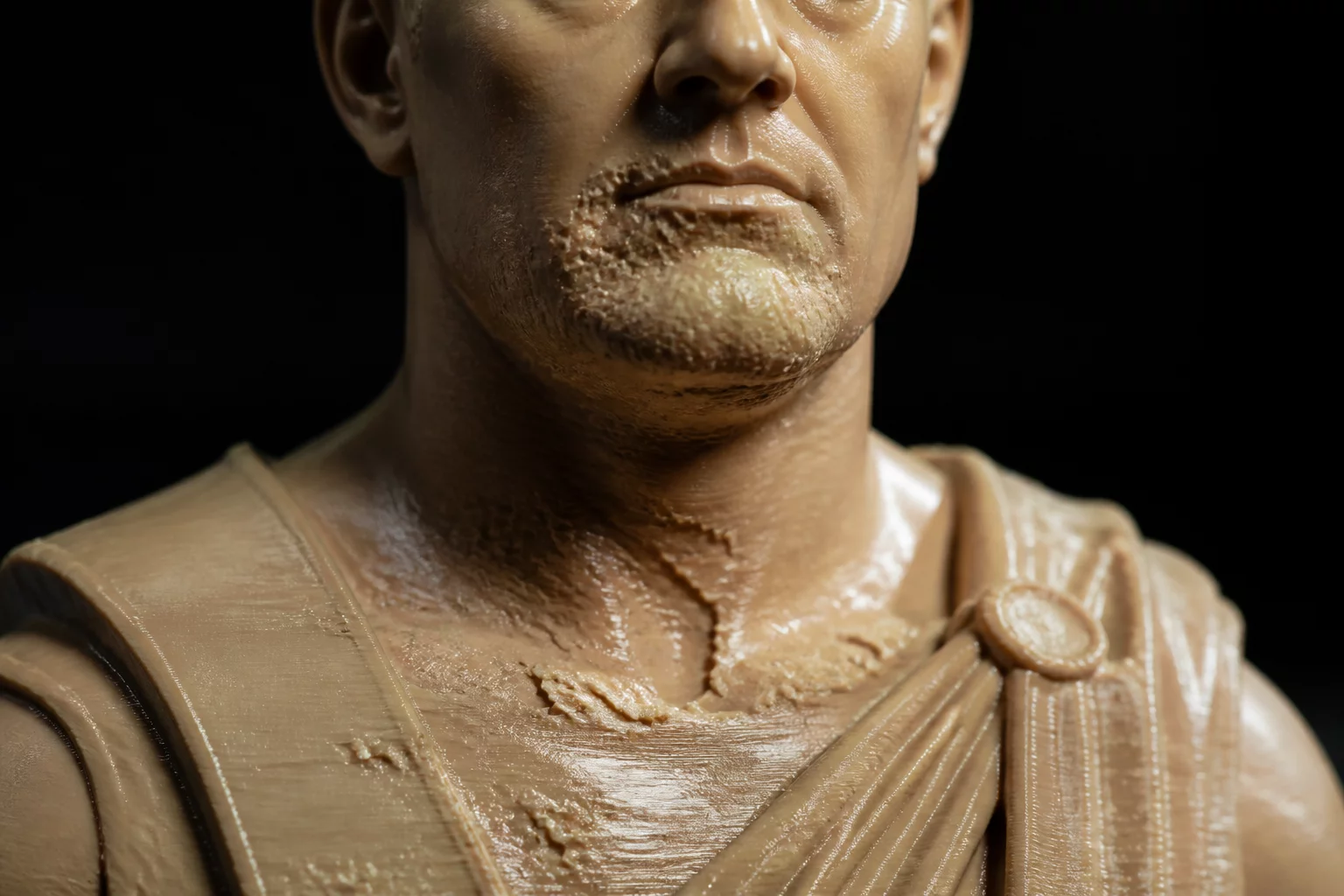
Every additive manufacturing build requires deliberate balance between structural continuity and cosmetic finish. During everyday 3D print orientation decisions, engineers routinely focus on sheer mechanical strength or rapid print cycles, often disregarding the cosmetic degradation left behind by breakaway interface contacts. When those contact points land directly on primary visible surfaces or mating datums, the post-processing effort increases exponentially.
In this specific diagnostic evaluation, a client housing component required an unblemished front fascia alongside tight internal slide tolerances. Initial automatic orientation placed heavy scaffolding across the primary aesthetic face to minimize overall build height. While this reduced total build time by eighteen percent, it created extensive pitting and localized delamination marks that manual bead blasting could not remediate without altering the dimensional profile.
Support Placement Diagnostics
A thorough PrusaSlicer orientation review revealed that tilting the part 37 degrees along the Y-axis shifted all support attachment points to interior non-functional ribs, preserving both visible surface integrity and mechanical rigidity.
Strategic Support Relocation
Resolving part orientation trade-offs demands categorizing every surface into primary aesthetic, fit-critical, or secondary hidden regions before slicing. By systematically prioritizing external cosmetic planes, you can force support generations onto sacrificial planes or internal cavities where cosmetic scars have zero impact on assembly performance.
- Identify all cosmetic Class-A faces and lock them as support-free zones using custom paint-on blockers.
- Reorient the build model so overhang vectors fall on structural reinforcement gussets or hidden inner cavities.
- Adjust top contact Z-distance to 0.2 mm with organic tree supports to minimize residual contact scar depth.
Balancing Surface Finish Against Build Time
While tilting the component increased total layer count, the resulting print eliminated three hours of manual sanding and chemical vapor smoothing per unit. Factoring downstream labor into the production calculation proves that dedicating extra machine time to clean orientation delivers a superior overall manufacturing workflow.
Dr. Julian Vance
Additive SpecialistWhen optimizing mechanical components under cantilever loads, aligning the tensile vectors parallel to the continuous build plate path yielded an impressive 42% reduction in shear cleavage failure. The anisotropic breakdown matrix presented here provides absolute clarity for production-grade engineering.