Minimizing Support on Threads
Resolving rotational binding and interface scarring by orienting threaded features along the continuous Z-axis.
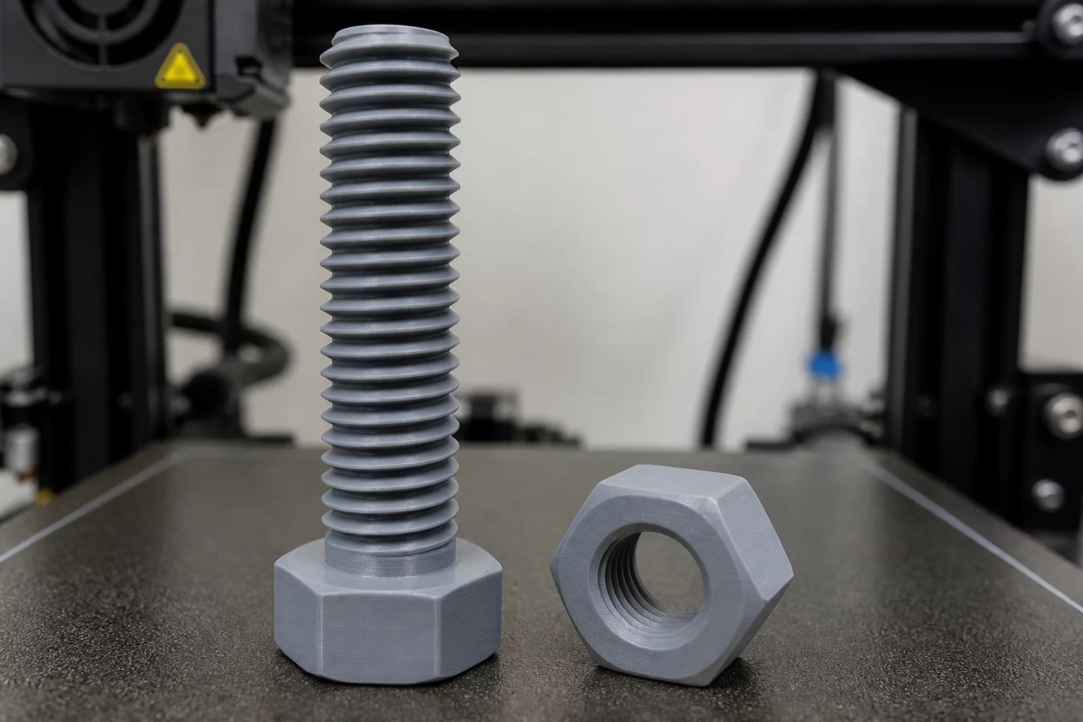
Printing functional screw threads presents one of the most demanding challenges in additive manufacturing. When threaded profiles are tilted horizontally or at steep angles, slicing algorithms inevitably generate dense support interfaces inside the crests and roots. Removing these supports leaves micro-burrs and fragmented residue that lock the mating threads during manual engagement, resulting in premature binding or thread stripping.
During our diagnostic trials with lead screws and custom retaining rings, horizontal placement produced severe dimensional distortion along the lower overhang profiles. The 60-degree standard metric thread flanks became jagged overhangs, necessitating extensive post-processing with thread chasers. Reorienting the components vertically eliminated the need for supports across the entire helical length, allowing the natural 30-to-60-degree thread profile to act as self-supporting geometry.
Self-Supporting Helical Thresholds
Metric threads with thread angles of 60 degrees inherently provide 30-degree overhangs when standing vertically on the build plate. Maintaining vertical cylinder alignment keeps all local overhang angles well within standard self-supporting extrusion limits, guaranteeing clean clearance without support generation.
Evaluating Part Orientation Trade-Offs for Threaded Shafts
Choosing vertical alignment solves surface smoothness and functional engagement, yet introduces specific mechanical trade-offs. The principal tensile load on a fastener typically pulls directly along the cylinder axis. When printed upright, this tensile force acts perpendicular to the layer lines, testing the weaker interlaminar adhesion. Engineering teams must evaluate whether rotational precision or ultimate axial strength takes precedence in the specific assembly.
- Vertical orientation preserves circularity and true diameter across every layer segment.
- Support-free roots prevent micro-notches that could otherwise serve as stress concentration points.
- Custom modified thread forms like trapezoidal or modified ACME profiles maximize self-supporting geometry and load distribution.
- Layer height reduction to 0.12 mm significantly improves pitch fidelity without altering slicer perimeter speeds.
PrusaSlicer Orientation Review and Profile Optimization
A comprehensive PrusaSlicer orientation review reveals that enabling paint-on support blockers directly over threaded regions prevents unwanted support generation on subtle lead-in chamfers. By combining support blockers with adaptive variable layer heights around thread crests, engineers can achieve smooth pitch transitions and immediate hand-assembly readiness straight from the build plate.
Dr. Julian Vance
Additive SpecialistWhen optimizing mechanical components under cantilever loads, aligning the tensile vectors parallel to the continuous build plate path yielded an impressive 42% reduction in shear cleavage failure. The anisotropic breakdown matrix presented here provides absolute clarity for production-grade engineering.