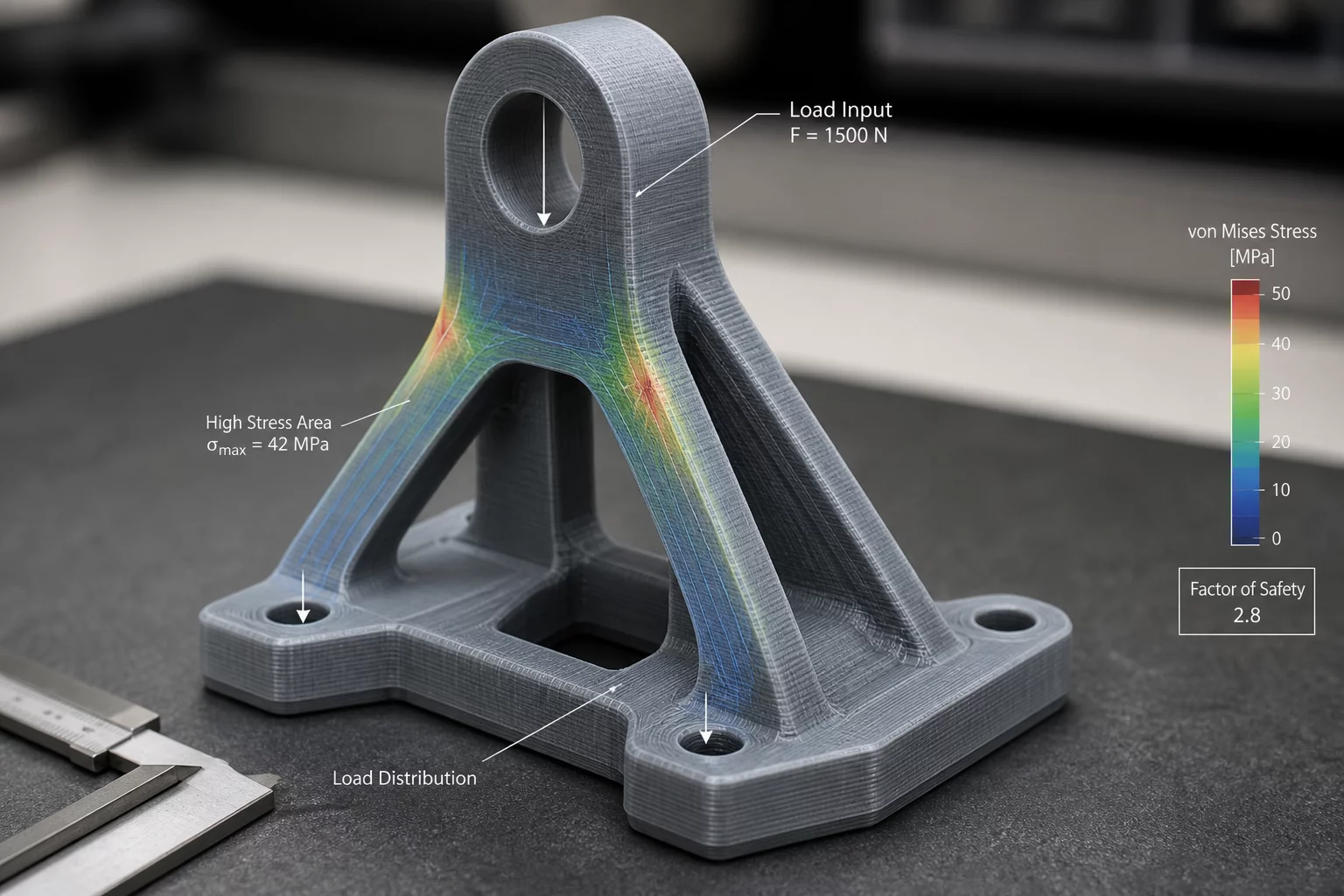
 Standard 01
Functional Direction
Aligning layer boundaries with anticipated load vectors resolves anisotropic shear vulnerabilities and reinforces primary stress axes.
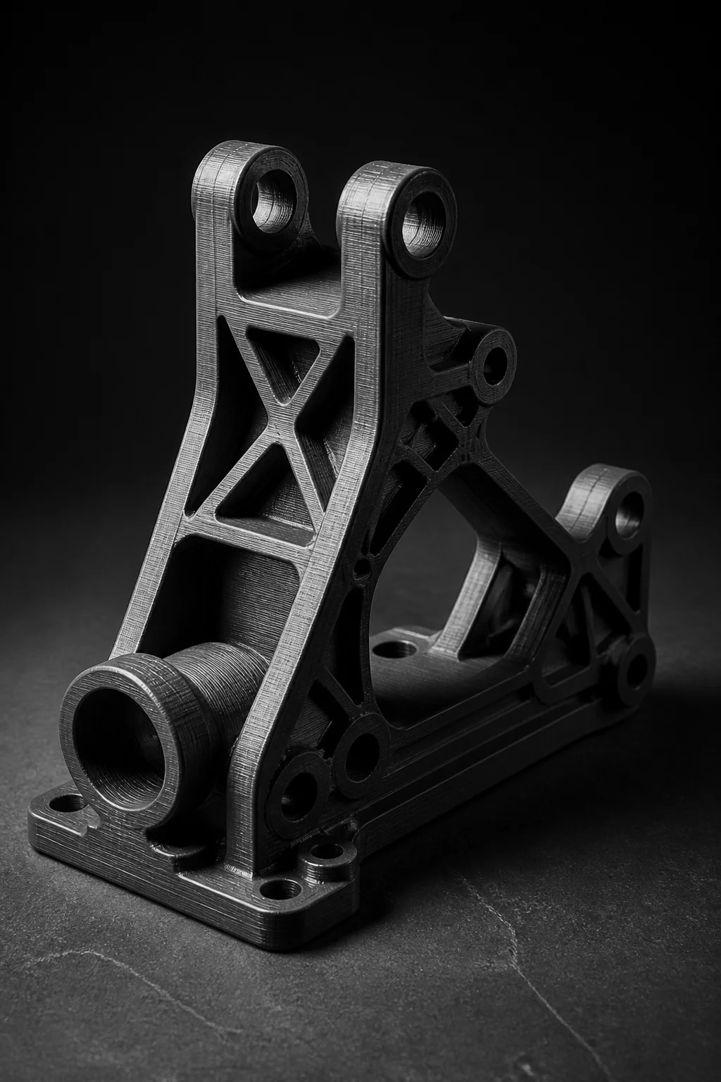

Z-Tensile Optimization
Compare surface quality, functional direction, support exposure, fit-critical features, and post-processing before selecting a print orientation.
Align critical structural loads along the continuous XY extrusion filaments instead of fragile interlayer Z bonds.
Orient cosmetic visual curves perpendicular to build layers to eliminate visible layer discretization steps.
Route unavoidable support structures toward concealed cavities and non-visible functional baselines.
Place mating bores and bearing journals upright on the Z axis to preserve cylindrical concentricity.
Mastering 3D print orientation decisions requires balancing tensile mechanical integrity against cosmetic layer stepping. By evaluating part orientation trade-offs before slicing, engineers protect critical tolerances and minimize post-processing friction during each PrusaSlicer orientation review.
Standard 01Aligning layer boundaries with anticipated load vectors resolves anisotropic shear vulnerabilities and reinforces primary stress axes.
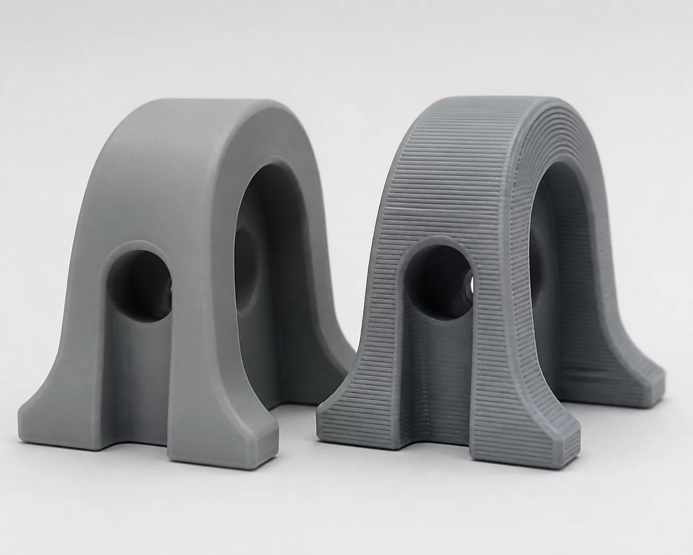 Standard 02
Strategically routing stair-stepping artifacts away from prime presentation facets preserves immaculate contour definition.
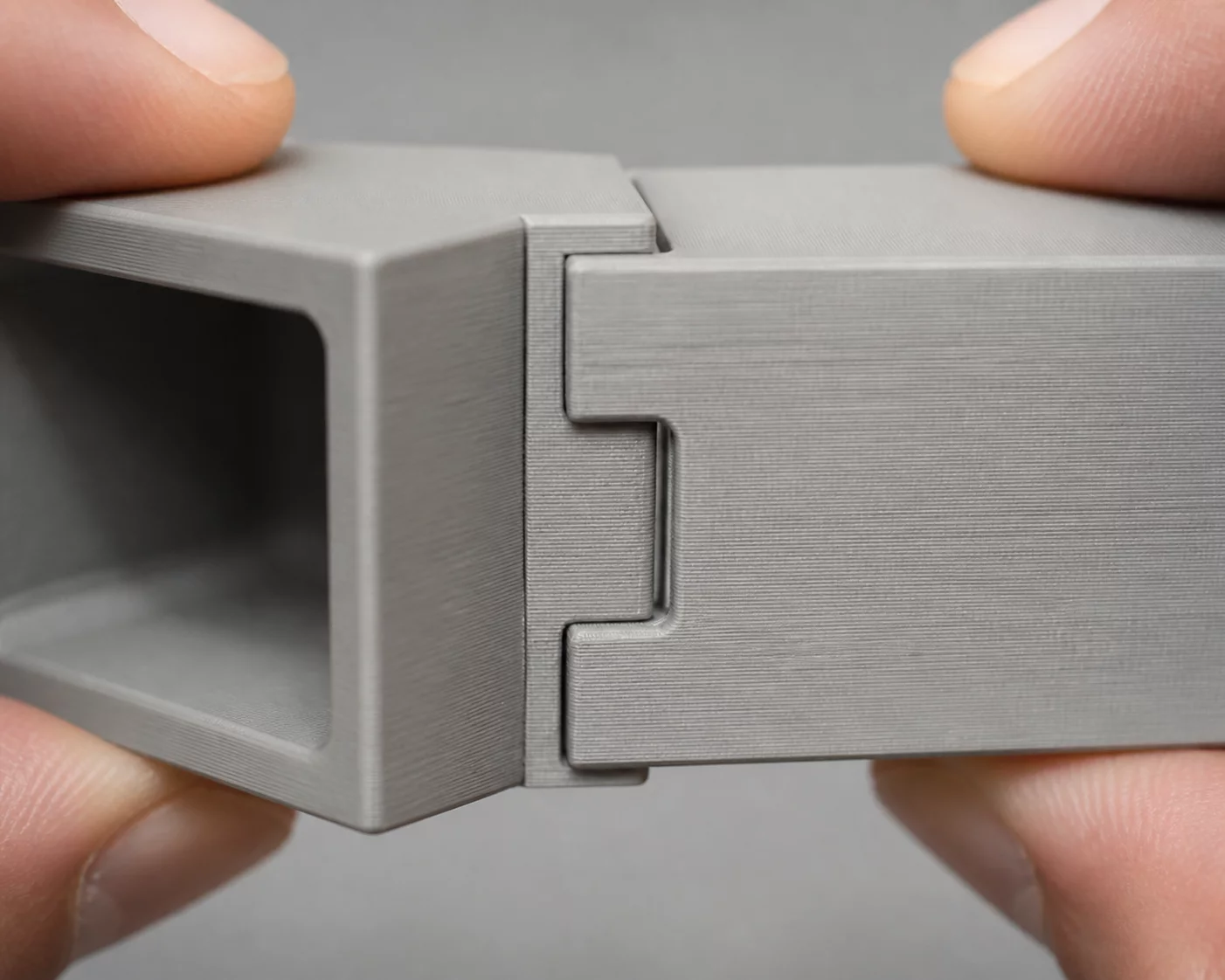 Standard 03
Protecting mating diameters and internal channels from support interfaces maintains exact mechanical coupling tolerances.
Explore real-world additive engineering teardowns comparing structural strength, interface tolerances, and post-processing trade-offs across distinct build angles.
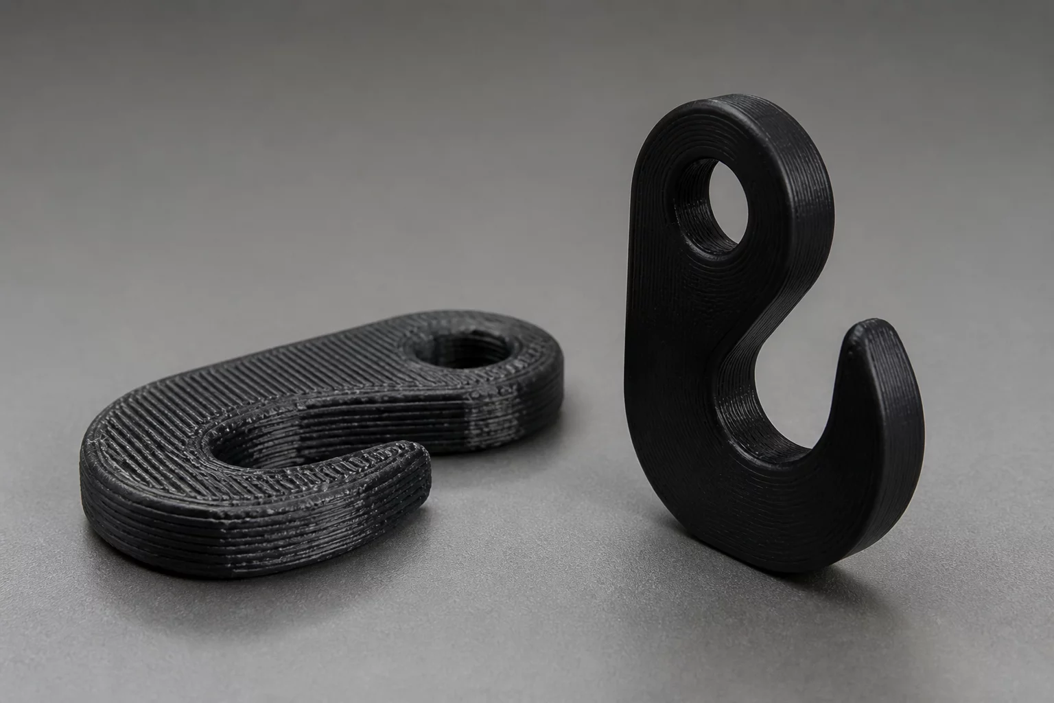 Strength vs Finish
An analytical comparison evaluating load-bearing hook performance printed flat versus upright cosmetic orientation.
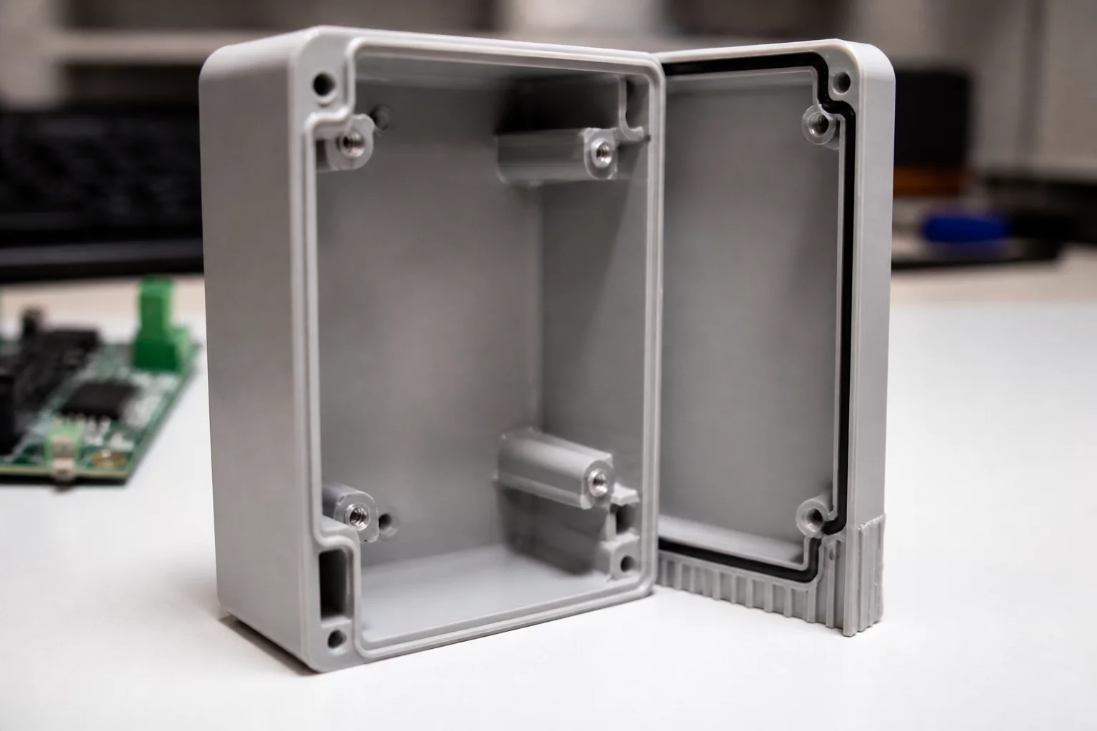 Fit Critical
Preventing support contact scarring on internal mounting posts and sliding contact surfaces for modular enclosures.
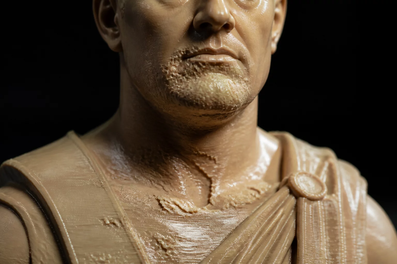 Surface Finish
Managing visual impact when support structures interface with visible display surfaces, curves, and cosmetic bezels.
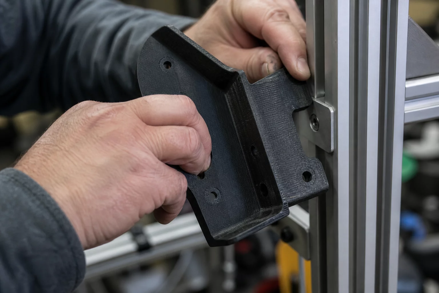 Tolerance Trade-off
Diagnosing thermal shrinkage, skew, and hole ovality when orienting for maximum tensile loading along layer lines.
A rigorous vetting checklist to verify technical maturity, evaluate critical part orientation trade-offs, and ensure functional reliability even if you decide to manufacture elsewhere.
Ensures the supplier calculates inter-layer shear stress instead of defaulting to the fastest build angle that compromises structural yield.
Checks if toolpath simulations are analyzed for steep overhang stability, bridging spans, and seam placement before physical manufacturing begins.
Identifies whether the contractor balances aesthetic layer stepping against shear resistance or blindly prioritizes visual cosmetics.
Horizontal holes often suffer from drooping roofs and polygon approximation, requiring specialized compensation or perpendicular orientation.
Improper interface layer count and contact distances lead to either surface scarring or unrecoverable sagging on critical mating flanges.
Evaluates bed adhesion control and chamber temperature uniformity to prevent corner lifting on high-aspect-ratio engineering builds.
Critical manufacturing and orientation terminology decoded into clear one-line definitions for engineering precision.
The variation of mechanical strength by direction, causing prints to fail significantly faster along layer bonds than across solid filament paths.
The visible terraced ridges on shallow curved geometry caused by slicing 3D models into discrete, flat planar layers.
The deviation of a surface from vertical, beyond which molten filament sags without sacrificial scaffolding structures.
The primary axis of operational stress positioned parallel to continuous extruded toolpaths to prevent premature shear failure.
Hydraulic vacuum forces generated when printing hollow cavities face-down against vat release films in resin photopolymer systems.
The vertical line of surface irregularities created where each perimeter loop begins and stops on the exterior envelope.
Master the complete decision framework in our comprehensive guide or explore real-world production cases.
Submit your component parameters for an expert analysis on mechanical strength, surface finish, and support minimization.