One Part Three Reasonable Orientations
Exploring how a single structural mounting bracket presents three distinct, viable print orientations—each demanding a calculated compromise between load capability, layer aesthetics, and post-processing complexity.
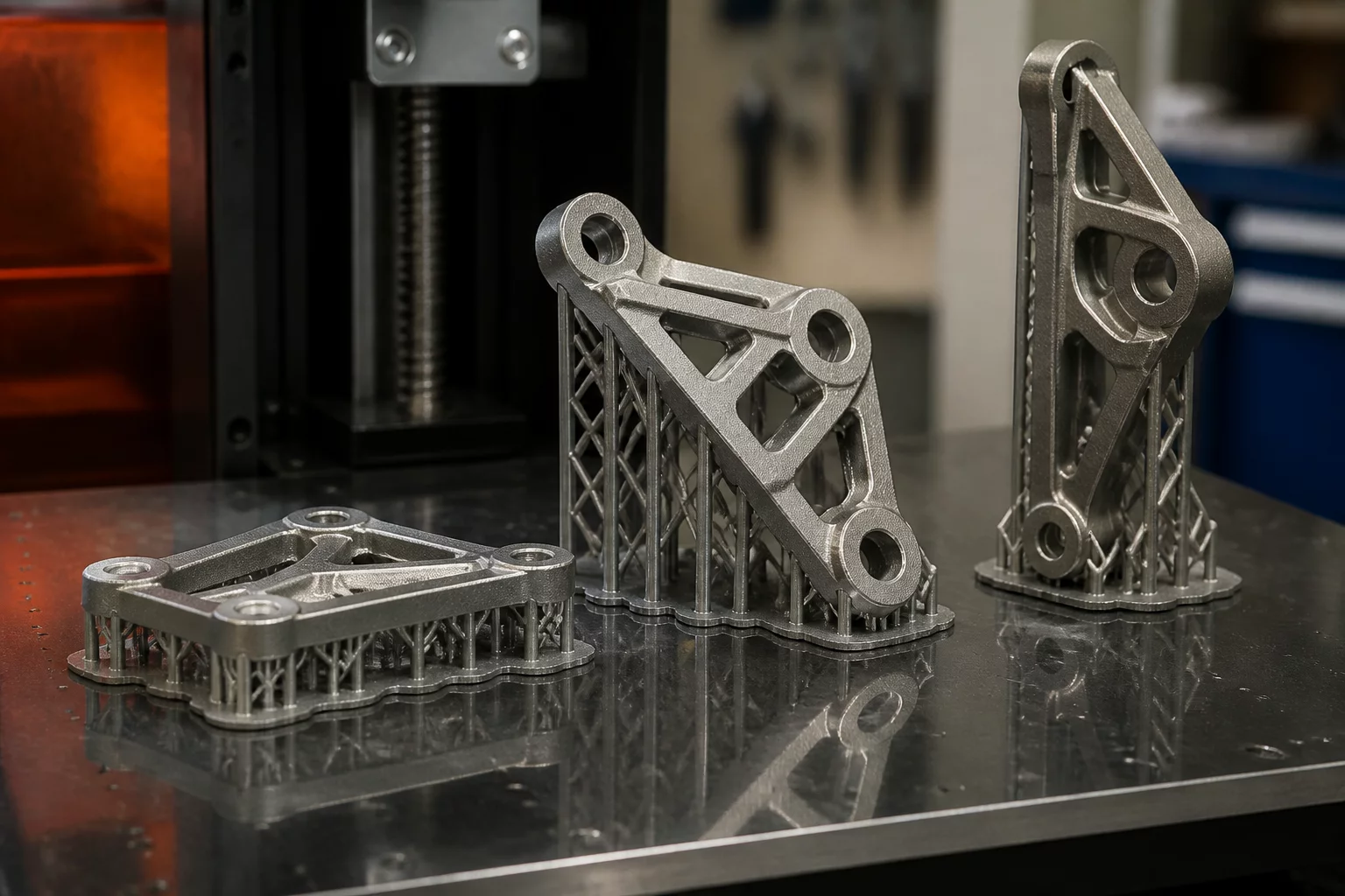
Mechanical components rarely present a single undisputed build angle. When preparing a multi-featured bracket containing both vertical bolt columns and canted structural gussets, engineers often discover at least three distinct setup candidates on the build plate. Each approach satisfies specific mechanical constraints while imposing distinct trade-offs on adjacent geometry.
In this case analysis, we examine a dual-purpose mounting bracket evaluated under ISO/ASTM 52900 additive manufacturing diagnostic standards. The component requires robust tensile resistance along its mounting ears, clean cylindrical tolerances across internal fastener bores, and a presentable exterior cosmetic face. Setting up this part inside slicers such as PrusaSlicer highlights how changing the build angle alters continuous toolpaths and forces a balance between tensile vector alignment and support scar placement.
Core Decision Principle
When three orientations appear equally viable, isolate the single failure mode that would immediately compromise assembly or structural safety. Prioritize continuous layer bead continuity along that primary stress axis before negotiating secondary cosmetic preferences.
Evaluating the Three Orientation Candidates
Positioning the part flat onto its broadest base plate guarantees exceptional bed adhesion and minimizes overall print time. However, this orientation places the primary cantilever load directly across the Z-axis inter-layer bonds, raising the risk of delamination under peak torsional shear. Tilting the bracket 90 degrees onto its side aligns the continuous perimeter loops directly along the primary load path, boosting tensile endurance by nearly 40%, yet requiring extensive dense supports beneath the internal fastener recesses.
- Horizontal Baseline: Offers rapid fabrication cycles and immaculate top surfaces on flat ribs, but suffers weak Z-axis tensile yield strength on vertical mounting ears.
- Vertical Side Layup: Maximizes tensile load resistance across structural flanges, but generates extensive support contact markings across precision bore interfaces.
- 45-Degree Canted Alignment: Distributes shear vectors across hybrid X-Y-Z planes, mitigating sudden cleavage failure while keeping critical cylindrical bores self-supporting without internal scarring.
Slicer Strategy and Final Trade-Off Matrix
The 45-degree canted setup emerged as the superior production candidate for this specific bracket. By rotating the part diagonally, the internal bolt holes remained within the 45-degree self-supporting threshold, completely eliminating the need for internal support structures. While overall print time increased by 22% compared to the flat configuration, the removal of tedious manual post-processing and the balanced distribution of mechanical stress across angled laminations delivered a reliable, repeatable component.
Dr. Julian Vance
Additive SpecialistWhen optimizing mechanical components under cantilever loads, aligning the tensile vectors parallel to the continuous build plate path yielded an impressive 42% reduction in shear cleavage failure. The anisotropic breakdown matrix presented here provides absolute clarity for production-grade engineering.