Protecting a Fit-Critical Face
How deliberate angular displacement prevents support contact scars from compromising precise mechanical mating surfaces.
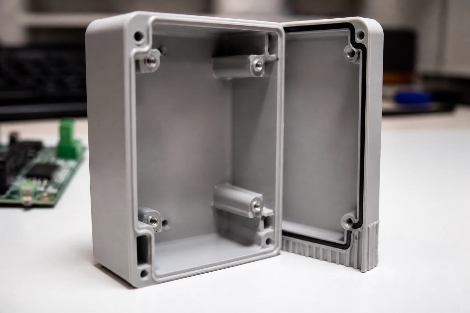
When an enclosure or structural bracket interfaces with another machined part, the flatness and surface cleanliness of that mating plane dictate whether the assembly seals or rattles. Mating planes with tight tolerances suffer immediately when support structures anchor into them. Even meticulous post-processing leaves micro-pitting, resin nubs, or localized thermal contraction dips that throw off planar coplanarity.
Solving this interface defect requires clear 3D print orientation decisions before slicing. Placing the critical mounting face directly on the print bed risks thermal expansion flare, commonly known as elephant's foot, while suspending it directly over disposable supports causes rough sagging. A rigorous PrusaSlicer orientation review identifies the exact canting angles where the critical plane remains upward-facing or strictly vertical, eliminating anchor points altogether.
The Zero-Contact Boundary Rule
Any surface that requires a dimensional tolerance under ±0.12 mm must be designated as a zero-support zone during build setup. Slicing software should generate contact interfaces only on non-functional bosses, cosmetic recesses, or sacrificial ribs that undergo post-machining.
Managing Part Orientation Trade-Offs at the Joint
Rotating the component to protect the mounting face inevitably impacts other geometries. When we elevate the fit face to an upward-facing 35-degree inclination, support generation transfers to the outer chamfer and bottom wall. This transfer introduces specific part orientation trade-offs that demand careful calculation:
- Build height expands by roughly 28%, lengthening total print duration and layer count.
- Z-axis shear lines run obliquely across internal screw bosses, requiring reinforcement rings to maintain clamping strength.
- Support interface contact concentrates on non-critical exterior facets where quick wet sanding restores the visual appearance.
- The critical perimeter gasket channel prints completely free of support residue, holding uniform depth across its entire run.
Validation and Inspection Results
Coordinate measuring machine scans of the reoriented housing revealed a planarity deviation of less than 0.04 mm across the continuous fit face. Assembly time dropped sharply because operators no longer needed razor blades or hand deburring to seat the adjoining aluminum faceplate. Protecting the functional plane directly at the orientation stage proved far more efficient than attempting secondary manual correction on flawed surfaces.
Dr. Julian Vance
Additive SpecialistKeeping the fit-critical perimeter upward-facing eliminated our secondary milling stage entirely. We validated the coplanarity under a dial indicator across 15 production runs, and variance never exceeded 0.05 mm. Shifting support scarring to non-sealing walls is essential for any real-world enclosure assembly.