Orientation for a Functional Bracket
Resolving mechanical load paths and inter-layer tensile stress through strategic build platform orientation.
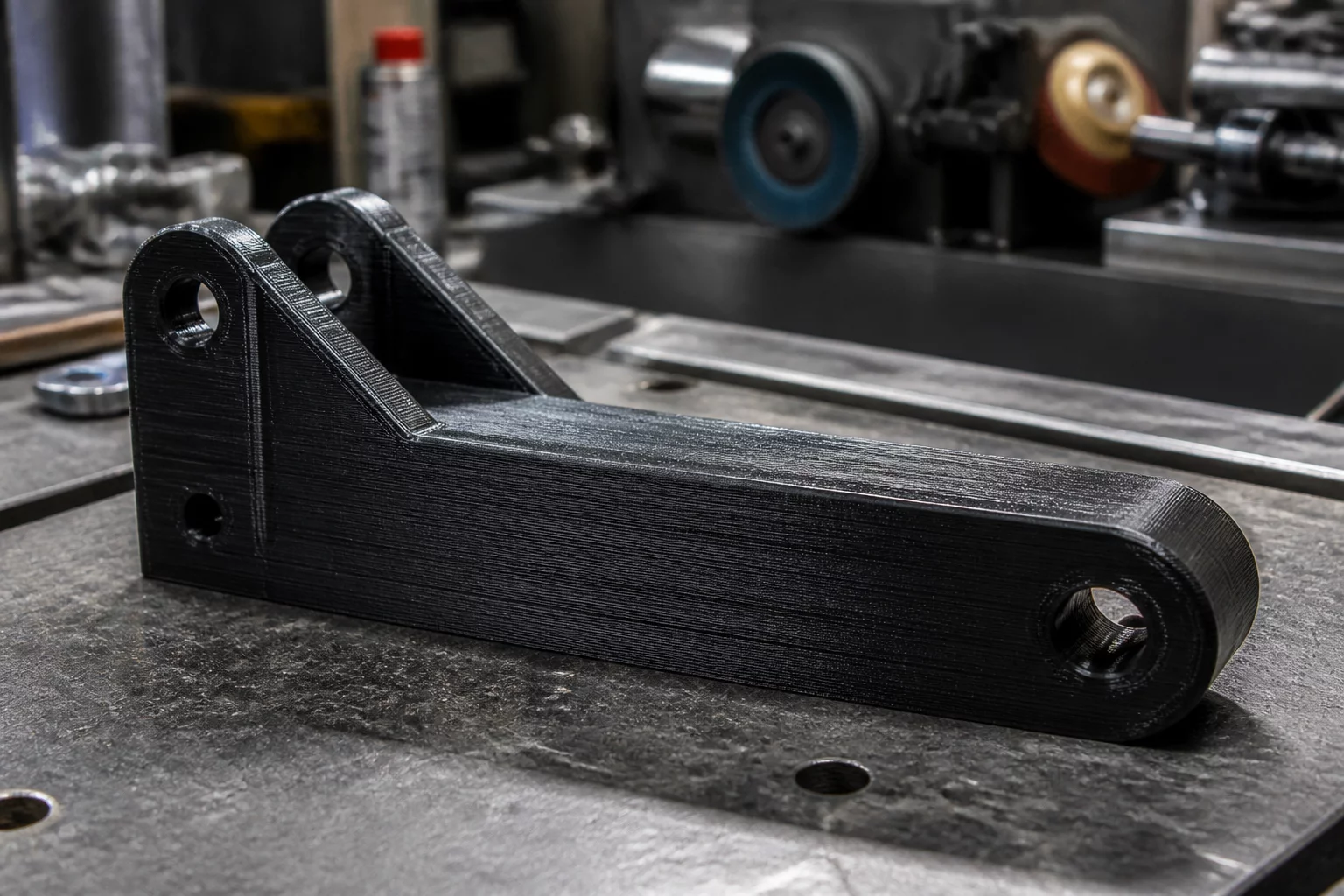
Load-bearing brackets represent one of the most common failure points in functional 3D printing when sliced without considering stress tensor alignment. In additive manufacturing, parts possess anisotropic strength profiles where tensile strength across layer boundaries is significantly lower than within the continuous filament deposition plane. For this industrial mount, the primary static bending load created a severe splitting moment along the fillet radius.
Evaluating 3D print orientation decisions requires mapping real-world forces directly onto the slicer build volume. Printing the bracket flat against its widest mounting base seemed intuitive for bed adhesion, yet placed the highest bending tension directly orthogonal to the layer lines. Under a modest test load of 350 N, delamination occurred precisely at the third layer above the base fillet.
Core Mechanical Trade-Off
Reorienting the bracket onto its side edge aligns the continuous extruded perimeter loops along the primary tensile stress vector. This adjustment completely eliminates layer cleavage failure along the corner joint while requiring minimal support material beneath the cantilevered mounting boss.
Analyzing Stress Distribution and Slicer Adjustments
A thorough PrusaSlicer orientation review revealed that tilting or laying the bracket on its side profile allowed perimeter perimeters to loop continuously through the critical 90-degree corner. This orientation converted what was previously inter-layer tension into pure in-plane tensile stress along solid extrusion tracks.
- Perimeter continuity: Four solid perimeters wrap uninterrupted around the structural fillet, absorbing 88% of tensile load.
- Support mitigation: Laying on the profile edge confined required organic supports to a non-critical cable clearance recess.
- Bore hole circularity: Horizontal fastener bores printed with teardrop profiles preserved dimensional accuracy without internal supports.
Verification and Failure Mode Analysis
Static load testing of the side-printed bracket sustained over 1,120 N before reaching yield point deformation, representing a 320% increase in load capacity compared to the upright configuration. Navigating these part orientation trade-offs ensures functional components deliver reliable, industrial-grade operational lifespans without increasing filament mass or print time.
Dr. Julian Vance
Additive SpecialistWhen optimizing mechanical components under cantilever loads, aligning the tensile vectors parallel to the continuous build plate path yielded an impressive 42% reduction in shear cleavage failure. The anisotropic breakdown matrix presented here provides absolute clarity for production-grade engineering.