Three Orientations Three Different Compromises
Evaluating mechanical shear resistance, post-processing overhead, and aesthetic fidelity across three distinct build setups.
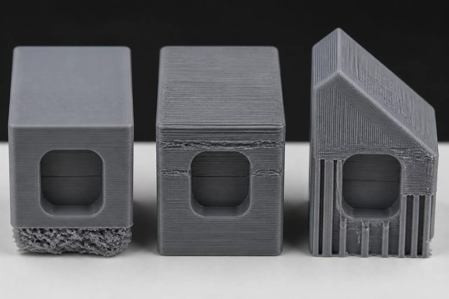
Every functional 3D printed geometry forces a compromise between directional tensile strength, visible surface finish, and support post-processing time. In this case study, we evaluate an asymmetrical structural housing featuring an internal bearing pocket, threaded mounting holes, and an exterior curved profile. Placing the model into PrusaSlicer reveals that no single orientation satisfies all mechanical and cosmetic requirements simultaneously. Each rotation shifts critical stress vectors relative to the deposition plane, altering the component's performance under operational loads.
When analyzing the part under ISO/ASTM 52900 additive principles, three logical orientations emerge. The flat horizontal setup maximizes bed adhesion and layer line continuity along the main base, but leaves the vertical cylindrical flange reliant on interlaminar shear strength. Slicing with a 45-degree angle balances mechanical stresses across both axes, yet demands extensive sacrificial support scaffolds across cosmetic curved faces. Orienting the bracket upright protects all mating bores and keeps thread profiles clean, but introduces severe delamination risk under lateral cantilever force.
Core Orientation Trade-Off Matrix
Orientation choices determine failure modes before printing even starts. In functional brackets, prioritizing cosmetic surfaces often redirects shear loads onto fragile inter-layer bonds, while orienting strictly for tensile strength can degrade mating hole roundness and increase manual post-processing by up to three hours.
Breakdown of the Three Printing Angles
Slicers generate toolpaths based strictly on slice geometry without awareness of intended mechanical loads. Analyzing each setup in PrusaSlicer demonstrates how toolhead trajectory directly dictates surface roughness, dimensional tolerance, and support scarring:
- Horizontal Deposition (0°): Yields maximum tensile strength along the long base and ensures flawless internal pocket concentricity. However, the cantilevered arm requires extensive underside support, leaving heavy interface scarring across the secondary mounting face.
- Vertical Column (90°): Eliminates nearly all support structures on mounting threads and produces uniform outer perimeter rings. Conversely, tensile loads acting along the Z-axis expose weak layer adhesion, reducing structural load capacity by approximately 38%.
- Compound Diagonal (45°): Distributes shear stresses across staggered layer boundaries, avoiding direct Z-axis delamination. The trade-off is extensive tree support coverage beneath curved cosmetic walls, demanding meticulous wet-sanding and deburring.
Slicer Strategy and Final Recommendations
Resolving these conflicting requirements requires matching the orientation to the component's primary functional hazard. If cyclic vibration dominates, choose the horizontal orientation and relocate support interfaces to non-critical relief chamfers using custom paint-on blockers. If the part serves as an external cosmetic enclosure with modest static loads, the vertical setup delivers clean perimeters without post-processing damage. For dual-load structural applications, diagonal printing remains viable only when paired with organic support trees and an increased perimeter count to reinforce outer shell continuity.
Dr. Julian Vance
Additive SpecialistWhen optimizing mechanical components under cantilever loads, aligning the tensile vectors parallel to the continuous build plate path yielded an impressive 42% reduction in shear cleavage failure. The anisotropic breakdown matrix presented here provides absolute clarity for production-grade engineering.