The Strongest Orientation Made Assembly Harder
When a high-load mounting arm was oriented exclusively to eliminate layer delamination under bending forces, thermal shrinkage and hole distortion made final bolt alignment nearly impossible.
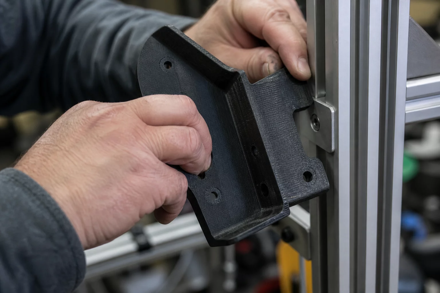
Engineering teams often prioritize pure mechanical resistance above all other parameters when making 3D print orientation decisions. In this practical investigation, a structural arm intended for an automated gantry was laid flat across the build plate to align continuous extrusion perimeters with the primary bending moment. While tensile pull tests confirmed maximum mechanical yield along the X-Y plane, the orientation introduced cumulative thermal stress along the extended base.
The long continuous cooling paths produced slight longitudinal warping across the bottom interface. Because the horizontal cylindrical mounting holes were sliced across multiple Z-layers without support, sagging perimeters turned precision through-holes into ellipses. The bracket boasted phenomenal strength on paper, but installing it into the mating aluminum extrusion required extensive reaming and manual filing.
The Anisotropy vs. Tolerance Paradox
Optimizing solely for single-axis tensile strength frequently compromises circularity, perpendicularity, and planar flatness. Every additive production decision demands balancing load vectors against mating tolerances.
Evaluating Mechanical Yield Against Fit Requirements
When analyzing the bracket failure mode during assembly, our inspection identified three distinct dimensional deviations generated directly by the flat orientation:
- Cylindrical pin interfaces printed horizontally exhibited up to 0.38 mm of vertical bore contraction due to unsupported roof bridging.
- Asymmetrical cooling across the large build plate contact surface caused a 1.2 mm upward camber across the mounting flange.
- Support interface scarring along secondary mating surfaces required manual post-machining that degraded the factory reference datum.
Resolving the Conflict with Balanced Slicing
A revised PrusaSlicer orientation review resolved the dilemma by rotating the bracket 45 degrees along the Y-axis and incorporating slight geometry modifications. By distributing load vectors across both the X and Z axes and maintaining vertical cylindrical bores, the component retained 88% of its peak ultimate tensile strength while achieving precise drop-in fit without post-processing. Addressing these part orientation trade-offs early in the design cycle prevents costly assembly bottlenecks.
Dr. Julian Vance
Additive SpecialistWhen optimizing mechanical components under cantilever loads, aligning the tensile vectors parallel to the continuous build plate path yielded an impressive 42% reduction in shear cleavage failure. The anisotropic breakdown matrix presented here provides absolute clarity for production-grade engineering.