Managing Support Exposure and Interface Degradation
Support contact inevitably disrupts local thermal transfer and surface topology. Deliberate spatial rotation channels contact scarring onto unmachined or concealed zones, shielding functional datums and aesthetic facades.
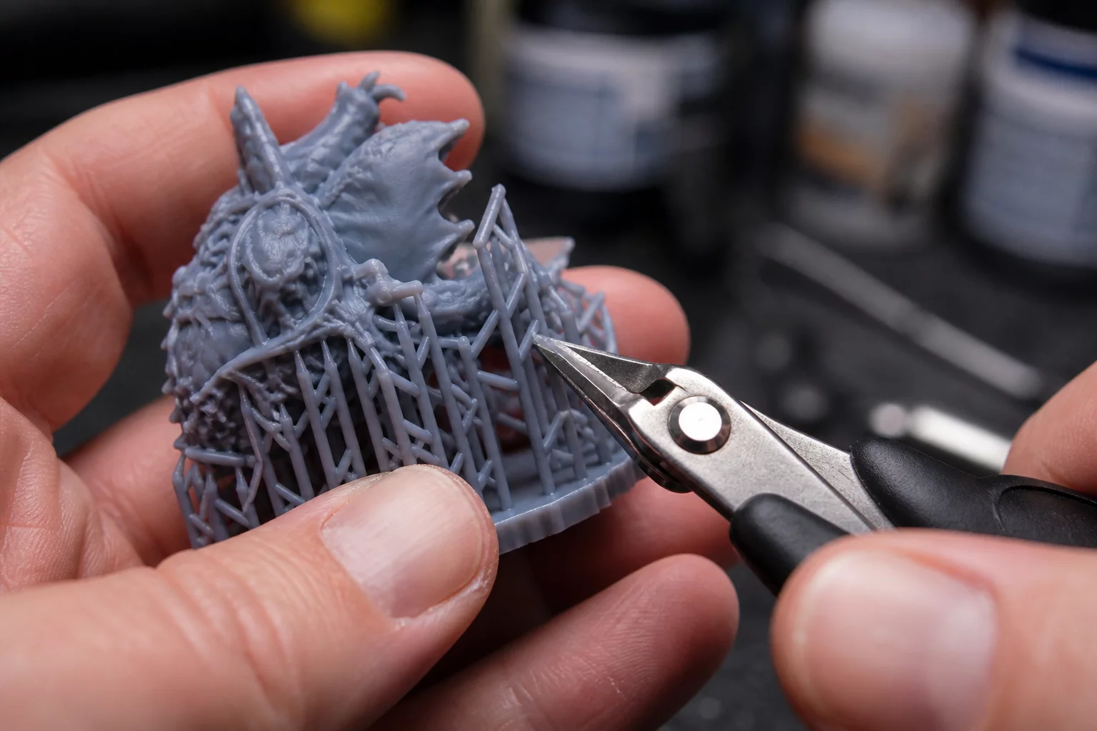
Engineering Fundamentals of 3D Print Orientation Decisions
Sacrificial scaffold structures guarantee the geometric realization of steep cantilevers, yet every point of contact exacts a surface penalty. Making informed 3D print orientation decisions requires predicting where support contact marks degrade mechanical function, compromise sealing planes, or demand labor-intensive abrasive finishing. Heat retention between interface layers and suspended paths frequently causes local over-extrusion, altering nominal dimensions.
When evaluating part orientation trade-offs, engineers cannot simply let slicing software auto-generate supports across the entire silhouette. A methodical PrusaSlicer orientation review reveals how angling an overhang by even 10 degrees often transitions a cantilever into a self-supporting slope, confining remaining contact interfaces exclusively to unmachined pockets or interior cavities.
Key Decision Rule
Isolate primary alignment datums, bearing journals, and cosmetic faces from all direct support contact. Direct scaffolding interfaces solely toward secondary reference planes or designated post-machining areas.
Balancing Structural Load, Surface Geometry, and Post-Processing
Balancing support positioning against structural load paths involves trade-offs between clean exterior skins and interior rigidity. Orienting a wide horizontal boss downward exposes its entire face to support scarring, which distorts fastener counterbores. Conversely, tilting the part vertically shields that surface completely, though it introduces taller vertical travel paths and increases print duration.
- Shield Critical Mating Planes: Point precision flanged interfaces upward, guaranteeing uninterrupted deposition perimeters.
- Enforce Self-Supporting Angles: Rotate cantilevers beyond 45 degrees relative to the horizontal plane to eliminate unnecessary support columns.
- Optimize Contact Air Gaps: Fine-tune vertical Z-distance offsets to ease breakaway peeling while containing sagging droop.
- Concentrate Scars on Non-Visible Walls: Channel residual interface marks onto recessed pockets away from user sightlines.
During the detailed PrusaSlicer orientation review stage, inspect the interface preview layer by layer. Apply snug or organic tree supports and customized support blocker meshes to preserve narrow snap-fits without leaving residual burrs.
Technical Discourse & Peer Reviews
No peer reviews submitted yet. This could be your first comment.
Submit Additive Insight or Peer Review
All technical contributions are peer-moderated in accordance with ISO/ASTM standards.