Dimensional Priorities
A systematic engineering approach to prioritizing fit-critical features across continuous planar toolpaths and vertical discrete layer heights.
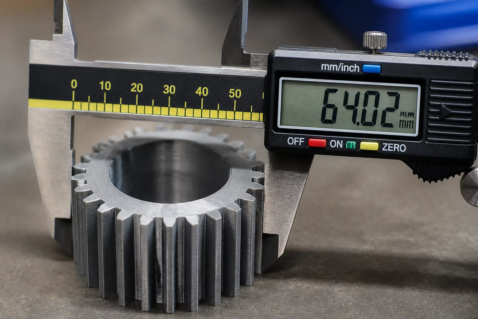
Engineering Fundamentals of Dimensional Priorities
Additive manufacturing builds components through layer-by-layer accumulation, creating an inherent divergence between continuous planar motion and stepped vertical indexing. Making sound 3D print orientation decisions requires identifying which geometric tolerances dictate component assembly before sending files to production.
Evaluating part orientation trade-offs means recognizing that circular journals and pin bores printed parallel to the build platform achieve true geometric roundness via smooth motion control. When rotated along the vertical axis, circular apertures are sliced into discrete stair-stepped segments, causing chordal errors and tightening nominal clearances. A structured PrusaSlicer orientation review enables designers to isolate primary mating interfaces and place them along the most accurate mechanical vectors.
Metrology Priority Directive
Assign priority to internal bore roundness and sealing surfaces by aligning their centerline vectors perpendicular to the print bed. For long slender spans, align length vectors along the XY plane to prevent cumulative Z-layer thermal contraction drift.
Managing Anisotropic Shrinkage and Stepping Discretization
Every coordinate axis in additive manufacturing demonstrates unique volumetric shrinkage characteristics. Linear polymer crystallization in the XY plane differs substantially from thermal relaxation across inter-layer Z boundaries. Prioritizing dimensional fidelity requires matching specific feature types to their ideal manufacturing axes:
- Cylindrical Journals and Bores: Position circular cross-sections in the horizontal plane to maintain radial roundness and eliminate support scarring on bearing surfaces.
- Precision Flat Datums: Print reference mating faces directly against the bed plate or parallel to top solid infill passes to guarantee planar parallelism.
- Slender Shafts and Pins: Align long structural pins horizontally when shear resistance is mandatory, or vertically when absolute diametrical roundness takes precedence.
- Interlocking Dovetails: Keep sliding interface profiles flat on the build table so extruded perimeter beads trace smooth unbroken sliding tracks.
Conducting a meticulous PrusaSlicer orientation review allows engineers to apply XY size compensation, elephant foot compensation, and seam alignment settings to protect tight dimensional tolerances across all mating features.
Technical Discourse & Peer Reviews
This could be your first comment. Share your metrology findings or orientation insights below.
Submit Additive Insight or Peer Review
All technical contributions are peer-moderated in accordance with ISO/ASTM standards.