Material Anisotropy in Additive Toolpaths
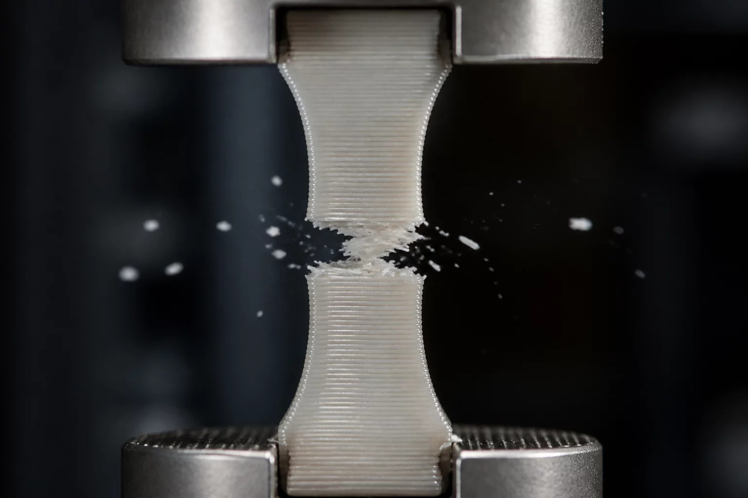
Layer-by-layer fabrication fundamentally transforms isotropic polymers into directional composite structures. Understanding material anisotropy is essential when aligning primary tensile and shear paths against build plane coordinates.
Engineering Fundamentals of 3D Print Orientation Decisions
Executing production-grade additive manufacturing demands an analytical framework that aligns mechanical vectors with geometric intent. Making informed 3D print orientation decisions is not simply a matter of minimizing slicer build time; it is the fundamental bridge between theoretical CAD geometry and real-world functional resilience.
When evaluating part orientation trade-offs, mechanical engineers must systematically assess anisotropic shear lines, staircase effects on cosmetic contours, and interface scarring on fit-critical surfaces. A thorough PrusaSlicer orientation review reveals that subtle 15-degree adjustments on the build table can dramatically redistribute layer boundary stresses away from failure-prone cantilevers.
Core Principle of Anisotropy
Inter-layer bond strength is governed by polymer diffusion kinetics at the melt interface. Never allow pure normal tension or peeling moments to resolve perpendicular to the build plate without reinforcing cross-perimeter perimeters.
Balancing Structural Load, Surface Geometry, and Post-Processing
Every component layout imposes a tri-fold compromise. Prioritizing peak tensile strength along horizontal filament runs frequently forces delicate curved surfaces onto shallow slopes where staircase discretization becomes visible. Conversely, tilting a part to eliminate visual stepping often introduces extensive overhangs requiring sacrificial support scaffolding.
- Continuous Perimeter Routing: Align continuous toolpaths along anticipated stress concentrations to prevent layer boundary cleavage.
- Diagonal Stress Redistribution: Cant components at 45 degrees to force cleavage planes across multiple interlocking raster layers rather than a single horizontal seam.
- Thermal Infiltration Optimization: Increase extrusion temperatures and reduce active part cooling on structural walls to expand the molecular fusion neck between adjacent vertical layers.
During the detailed PrusaSlicer orientation review stage, utilize variable layer height modifiers and custom support blockers to mitigate interface damage on critical dimensional journals while maintaining structural integrity.
Technical Discourse & Peer Reviews
No comments yet. Be the first to leave a comment and share your experimental findings.
Submit Additive Insight or Peer Review
All technical contributions are peer-moderated in accordance with ISO/ASTM standards.