Assembly Interfaces & Mating Geometries
Engineering precise mechanical connections across modular assemblies by eliminating support scarring on contact faces, controlling thermal shrinkage vectors, and optimizing raster alignment along interlocking joints.
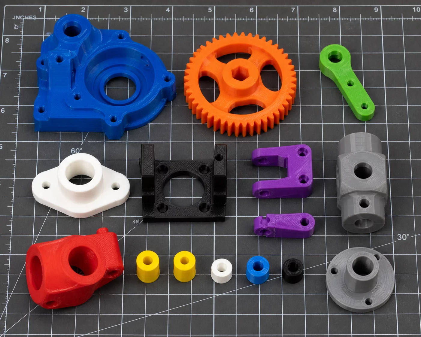
Engineering Fundamentals of 3D Print Orientation Decisions
Modular engineering designs frequently succeed or fail right at the connection interface. Making rigorous 3D print orientation decisions is essential when multi-part mechanisms require seamless press-fits, sliding dovetails, or repeatable snap joints without extensive manual scraping.
When evaluating part orientation trade-offs for mating components, engineers must prioritize bearing surfaces over cosmetic side walls. A thorough PrusaSlicer orientation review allows you to verify that contact planes remain untouched by sacrificial support material, preventing microscopic residual bumps from binding tightly matched components.
Assembly Interface Rule
Never place support interfaces on critical mating shoulders, alignment pins, or snap-fit hinge roots. Position sliding contact flats directly against the smooth build surface or along pure vertical planes where toolpath stepping remains uniform.
Managing Tolerances, Snap Compliances, and Interlocking Features
Interlocking mechanisms demand a methodical balance between geometric accuracy and mechanical compliance. Small dimensional deviations along the build axis alter fit clearances, converting free-moving joints into immovable interference fits.
- Snap-Fit Beam Direction: Lay flexure arms flat along the print bed so tensile bending forces act through uninterrupted extrusion loops rather than fragile interlayer seams.
- Dovetail Flatness: Align sliding tracks vertically or perfectly horizontal to avoid ragged staircase facets on sliding tapers.
- Pin Alignment: Build cylindrical locating dowels vertically for concentricity, while factoring in slight hole expansion compensations within the slicer settings.
- Thermal Shrinkage Balance: Orient mating shells in identical build directions to ensure thermal shrinkage percentages match on both halves.
During your practical PrusaSlicer orientation review, apply custom paint-on seam placement to tuck toolpath start points into internal relief grooves, preventing perimeter blobs from obstructing assembly clearance.
Technical Discourse & Peer Reviews
No comments yet. Be the first to leave a comment.
Submit Additive Insight or Peer Review
All technical contributions are peer-moderated in accordance with ISO/ASTM standards.