Post-Processing Considerations in Part Orientation
Minimizing bench finishing labor, avoiding contact scars on functional planes, and configuring geometries for streamlined chemical or mechanical surface refinement.
Engineering Fundamentals of 3D Print Orientation Decisions
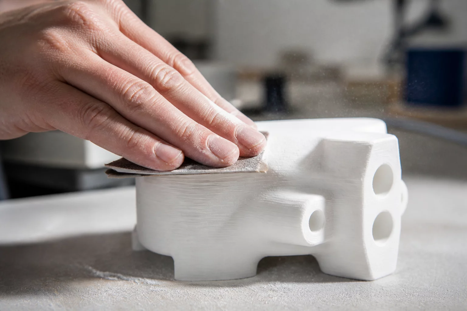
Executing production-grade additive manufacturing requires analyzing how component setup influences manual finishing. Calculated 3D print orientation decisions reduce post-processing bottlenecks by placing support contact points only on non-critical, easily accessible flat surfaces. Labor spent deburring, sanding, or chemical vapor smoothing can rapidly exceed the actual build cost when complex undercut geometry requires aggressive mechanical intervention.
When evaluating part orientation trade-offs, engineers must weigh the time required for post-print support removal against mechanical strength and layer stepping. A rigorous PrusaSlicer orientation review highlights how altering orientation by even 10 to 20 degrees shifts sacrificial interfaces to recessed pockets, preventing surface pitting on visible cosmetic faces and preserving nominal engineering clearances.
Key Decision Rule
Isolate all support generation vectors from mating registers, threads, and high-visibility cosmetic skins. Direct unavoidable support interfaces toward easily accessible planar faces where rotary sanding tools or solvent wipes can operate unobstructed.
Minimizing Manual Labor Through Toolpath and Scaffold Planning
Post-processing efficiency directly hinges on the interface distance and contact density chosen during preparation. Excessive contact area leaves stubborn residue that tears away parent material during removal. Insufficient support causes sagging overhangs requiring extensive filler putty and progressive grit sanding to restore nominal dimensions.
- Accessible Interface Planes: Place support contact points on open external perimeters rather than deep internal cavities where pliers cannot reach cleanly.
- Self-Supporting Chamfers: Rotate parts to utilize 45-degree self-supporting draft angles, eliminating scaffold structures on critical datum edges.
- Vapor Smoothing Grain Alignment: Orient parts so primary layer ridges run parallel to solvent drainage lines during chemical vapor polishing.
Conducting a comprehensive PrusaSlicer orientation review enables users to configure paint-on support blockers across threaded holes and intricate lettering, ensuring clean breakaway structures without manual scraping.
Technical Discourse & Peer Reviews
No peer insights submitted yet. Be the first to provide technical findings or post-processing feedback for this directive.
Submit Additive Insight or Peer Review
All technical contributions are peer-moderated in accordance with ISO/ASTM standards.