Part Stability and Build Bed Anchoring Dynamics
A fundamental guide to eliminating print bed detachment, thermal curling, and tall aspect ratio deflection by optimizing base contact area and center-of-gravity vectors.
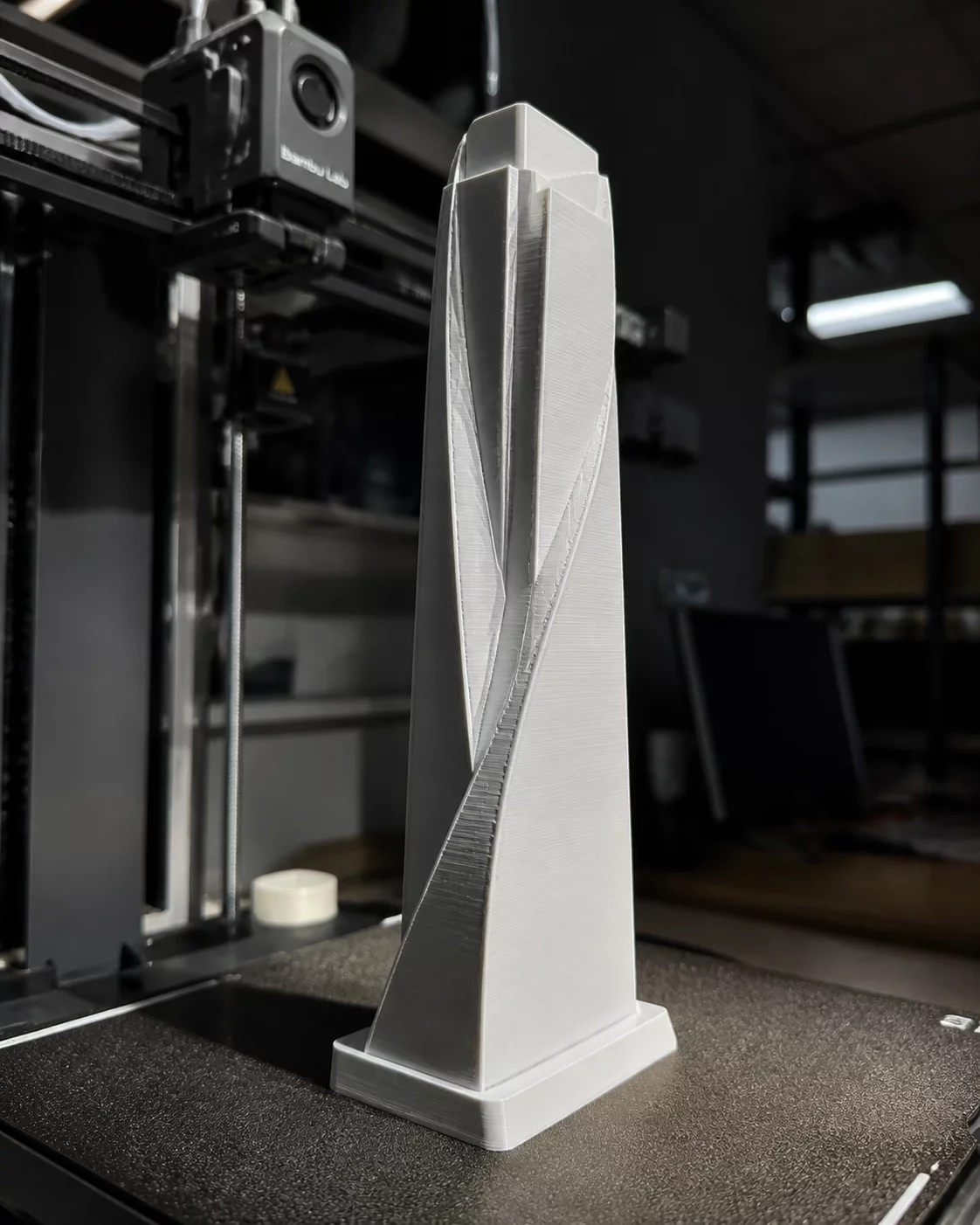
Engineering Fundamentals of 3D Print Orientation Decisions for Stability
Every additive manufacturing build succeeds or fails during the initial 20% of its vertical deposition cycle. When making calculated 3D print orientation decisions, preserving part stability on the build sheet takes precedence over purely cosmetic surface considerations. A model with an elevated center of gravity or a narrow base footprint will oscillate under high nozzle accelerations, causing layer-shifting defects or complete detachment from the heated bed.
Evaluating part orientation trade-offs requires balancing the contact footprint against thermal contraction stresses. Large planar surfaces exhibit significant warping moments at sharp corners as engineering thermoplastics cool, whereas slender upright structures suffer from dynamic nozzle shear forces. Conducting a systematic PrusaSlicer orientation review allows engineers to identify vulnerable aspect ratios and apply targeted brim reinforcement or orientation tilts before committing valuable machine time.
Stability Rule of Thumb
Maintain a height-to-base aspect ratio under 3:1 whenever possible. When tall vertical geometries are mandatory, lower print speeds above 50 mm/s and add integrated stabilization brims or support anchors to resist dynamic nozzle torque.
Balancing Bed Contact Area, Warping Vectors, and Acceleration Moments
Mechanical stability on the build plate depends on three interacting physical factors during the printing process:
- Base Surface Area: Maximize uninterrupted planar contact on the initial layer to create strong chemical and mechanical adhesion with the build sheet.
- Corner Chamfering & Radius: Sharp 90-degree outer corners concentrate thermal shrinkage forces, making rounded or chamfered footprints far less prone to lifting.
- Center of Mass Height: Keep the heaviest volumetric sections as close to the build plate as possible to diminish the lever arm created by horizontal kinematic moves.
- Cross-Sectional Transitions: Abrupt changes in layer area generate uneven thermal stresses that cause localized delamination and premature part tilting.
In your PrusaSlicer orientation review, examine the sliced preview using the volumetric flow rate and layer speed visualizers. Spotting sudden velocity changes at upper cantilevers helps you prevent the print head from dislodging slender standing geometries.
Technical Discourse & Peer Reviews
No peer reviews submitted yet. Be the first to provide technical observations for this orientation directive.
Submit Additive Insight or Peer Review
All technical contributions are peer-moderated in accordance with ISO/ASTM standards.