Print Stability: Anchoring Geometry Against Dynamic Build Forces
Maximizing build plate contact area, lowering center of gravity, and dampening nozzle shear moments during high-speed extrusion cycles.
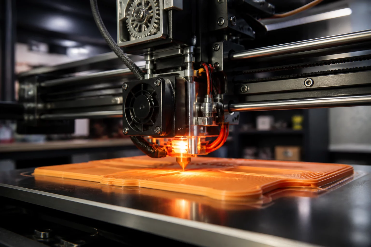
The Physics of Print Stability in Additive Manufacturing
Print stability represents the mechanical equilibrium between bed adhesion forces and kinematic disturbances during fabrication. Making calculated 3D print orientation decisions requires accounting for both static thermal contraction and continuous dynamic forces exerted by moving print heads. When a tall, slender part is built upright, the distance between the top deposition point and the build sheet acts as a mechanical lever, magnifying tiny nozzle contacts into catastrophic detachment moments.
Evaluating part orientation trade-offs means balancing footprint stability against cosmetic requirements and internal overhangs. A meticulous PrusaSlicer orientation review enables practitioners to inspect the center of gravity projection, simulate bed acceleration torques, and determine whether geometry requires auxiliary brims, sacrificial struts, or complete re-orientation to lower the build height.
Stability Threshold Metric
Maintain a minimum base-to-height aspect ratio of 1:3 for unsupported upright parts. Exceeding this ratio demands dedicated stability anchors or a 90-degree re-orientation to prevent nozzle-induced layer shifting.
Mitigating Dynamic Inertia and Thermal Peeling
As print speeds climb to 250 mm/s and beyond on modern core-XY and bed-slinger platforms, inertial acceleration shifts from a secondary factor to a primary failure mode. Bed-slingers present an asymmetrical risk: orienting slender parts with their narrow profile aligned to the Y-axis causes severe oscillations as the bed reciprocates violently.
- Kinematic Alignment: Orient the longest planar cross-section parallel to the primary bed movement axis on Cartesian bed-slinging machines.
- Thermal Anchor Mass: Provide expansive first-layer surface contact to withstand cumulative shrinkage stresses from engineering thermoplastics like ABS, ASA, and PA-CF.
- Conical Base Enlargement: Incorporate mouse-ears or chamfered support cuffs at high-stress base corners prone to localized lifting.
- Z-Hop Optimization: Configure micro-retraction lift during fast non-print traversals to eliminate nozzle grazing against high aspect ratio towers.
Conducting a rigorous PrusaSlicer orientation review allows engineers to evaluate the exact travel pathways and add custom stability blockers or organic tree supports that physically brace delicate upright vertical elements.
Technical Discourse & Peer Reviews
No comments yet. Be the first to leave a comment.
Submit Additive Insight or Peer Review
All technical contributions are peer-moderated in accordance with ISO/ASTM standards.